
DIY Guitar Overdrive - "The Tube Screams"
by Adam Fet • 2026-02-18
I love me some guitar pedals, as they are really simple circuits that don't require encyclopedic amounts of electronics knowledge in order to build correctly, nor do they demand rare components, so pretty much everyone should be able to build one from the comfort of their own home (unless we're getting into loopers and digital stuff in general).
This guide will (hopefully) walk you through the basics to build a simple Tube Screamer clone.
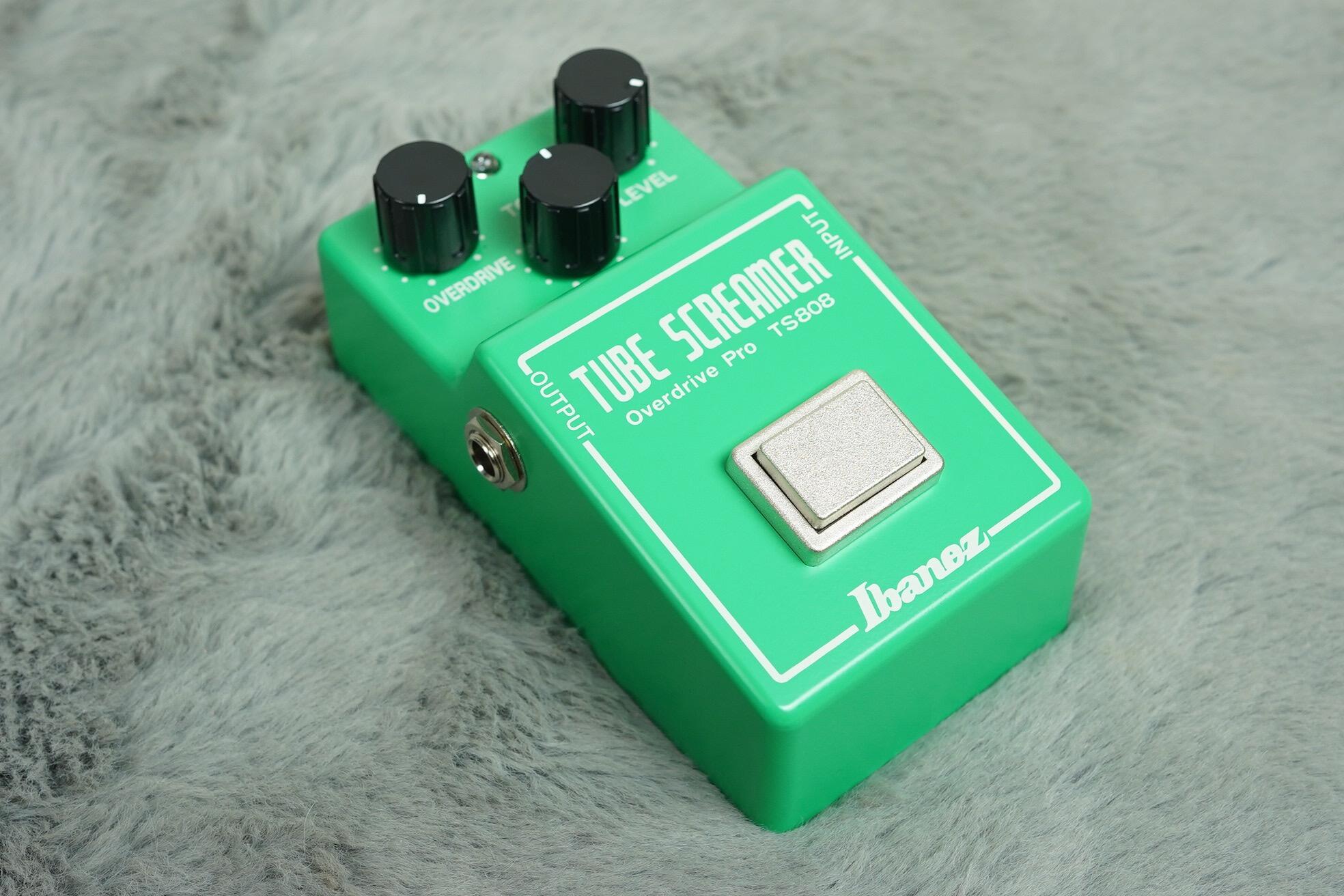
While I think the Ibanez Tube Screamer needs no introduction, here's some key points about its history:
- The base circuit has been around for decades at this point, since 1979 to be more precise.
- The circuit was originally designed to push already overdriven tube amps even harder, so it has a sort of "smoother" distortion.
- This is one of the, if not THE most cloned guitar pedal in the entire industry.
- There are more than 11 variations on the base circuit made by Ibanez themselves, but today we'll focus on the TS-808.
Now that we're done with some history lessons, let's get started.
The Build
I got this schematic from electrosmash, and it's what I'll be using to base my own design on:
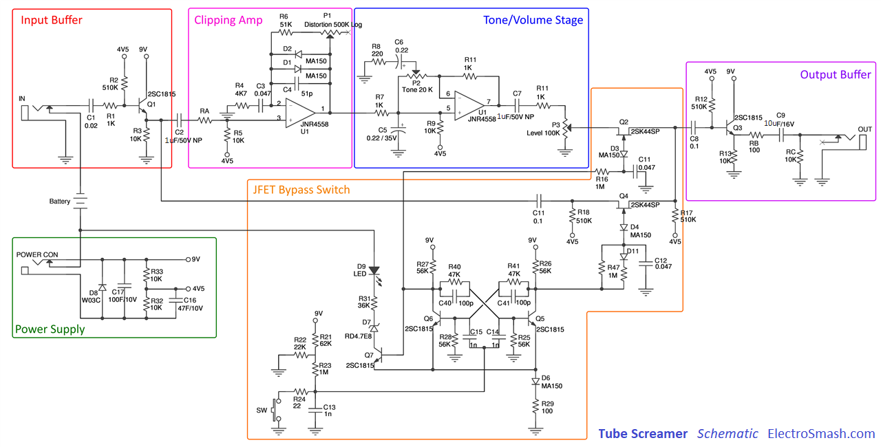
I tried to focus on designing an accessible circuit, so instead of going the full BJT buffer route for the input and output stages I based the entire thing around a single TL072 op-amp, which works great as it uses JFETs which are known to handle high impedance signals amazingly. I also skipped the entire switching circuitry, given that we're working on a breadboard (for now).
💡 Tip: you can click or tap the images to see them in a new tab!
Here's the TL072's pinout, which is standard for most dual operational amplifier chips.

And, of course, the circuit in question.

I'll try to explain what's going on in the image above by following the circuit from top to bottom, left to right, so try to keep the diagram handy while reading the next section.
Here's the gist of it all:
- The instrument's signal comes in through J1, it sees an input impedance of ~470k Ohm mostly set by R2
- Both C1 and R2 form an input high-pass filter that removes low frequency noise, well below 20Hz so that the audible spectrum remains untouched
- There's also an input low-pass filter which should handle high frequency noise induced by EMI, this is formed by R1 and C2 and lets 20KHz go through
- R2 also serves a second purpose, as it adds a DC bias to the signal at one half of the supply's voltage, in this particular case it sets a 4.5V bias given a standard 9V guitar pedal power supply (more details in the next section)
- Since we added a DC bias, C1 helps us block it so that it may never reach our guitar.
- Next is arguably the most important part of the circuit, the soft clipper. It uses one of the op-amps from the TL072 to buffer the input signal in a non-inverting configuration, then adds a whole lotta gain defined from *11 all the way up to *111, depending on RV1's value, so 1mV of input would go from 11mV to 111mV
- Both D1 and D2 are shorting the signal between the op-amp's output and it's inverting input, creating a clipping effect the closer the signal gets to their voltage drop value (~6V) and allowing us to get closer to that ridiculous value of *111 gain
Wow, that's a lot of stuff you just read! You deserve a small break, I'm proud of you 🤘.
- C3 allows the whole thing to work without blowing up, as it prevents the DC bias from being affected by the voltage divider set by RV1, R3 and R4, thus the op-amp doesn't work as hard trying to produce a multiple of it via its output
- Next is pretty simple, we pass the signal through a low-pass filter so that the added distortion doesn't sound as harsh to our ears. This one is set at around 15KHz, but you can play around with some values to get either a darker or brighter sound, check out this LPF calculator!
- Moreover, you could replace R5 with yet another potentiometer and use it as a tone control
- The filtered overdriven signal is buffered by out trusty TL072 and then goes out to a simple volume potentiometer, which acts as a simple voltage divider
- Take note that RV2 is also dividing the DC bias we added at the input stage, but this shouldn't suppose a problem as C5 allows us to block that DC so that we aren't loading whatever we connect this circuit to next, be it an amp, DI box or guitar pedal
- Finally, we add R6 to act as a drain for C5, this also acts as a high-pass filter so we select a value that won't affect 20Hz, in this circuit I chose 100K Ohm, which should give us plenty of room
- Our signal meets the outside world with J2!
Do take note that I'm using logarithmic potentiometers for both RV1 and RV2, the build will work just fine with linears (which are much easier to find in any electronic components store), but it may sound a bit off.
That's most of the processing explained in some "simple" bullet points, but we still have to talk about how we're powering this thing in a bit more detail:
- I'm assuming this circuit will be powered by a standard guitar pedal power supply (9V DC), but it should work with either lower or higher voltages, but keep in mind that lower voltages will limit the effective dynamic range for the signal processing, so it will clip much sooner
- R7 and R8 create a voltage divider that should get us close to half the power supply's voltage, we'll use this to create our DC bias as mentioned above
- We're also adding 2 capacitors: C6 and C7 which smooth out the DC a bit
- Finally, we connect out power rails (9V and GND) to our TL072 to power the whole thing
That's it! Feel free to try it out and build it yourself.

Sound demos
Check out what the effect sounds like at a couple of "Drive" levels!
| Clean | DI | Amp |
| FX at 0% | DI | Amp |
| FX at 50% | DI | Amp |
| FX at 100% | DI | Amp |
Note: All files were normalized to -3dBTP using ffmpeg before their publication.
Thanks!
Thank you for reading! ♥
Hopefully you enjoyed your stay here, I'll try to write up some new guides as I release videos so keep your eyes open!
If you enjoy my work, you can always contact me via email or gift me a coffee, I do appreciate it a whole lot!
Sources
- Classic gear: Maxon Overdrive and Ibanez Tube Screamer
- Cause & Effects: Tube Screamer season has arrived - but why do guitarists love this pedal so much?
- Ibanez Tube Screamer History
- The Technology of the Tube Screamer
- Tube Screamer Analysis
- TL07xx Datasheet by Texas Instruments
- TL072 Pinout Diagram by CircuitsDIY on Pinterest
- TS808 header picture by ATBGuitars.com