
DIY Guitar Distortion - "Mouse 2"
by Adam Fet • 2026-03-25
Heyo fellas, we're back at it again with another CRAAAAZY guitar effect build.
This time, we're building a distortion effect, which is pretty darn similar to overdrive in the general behavior of the circuit (as seen in this video).
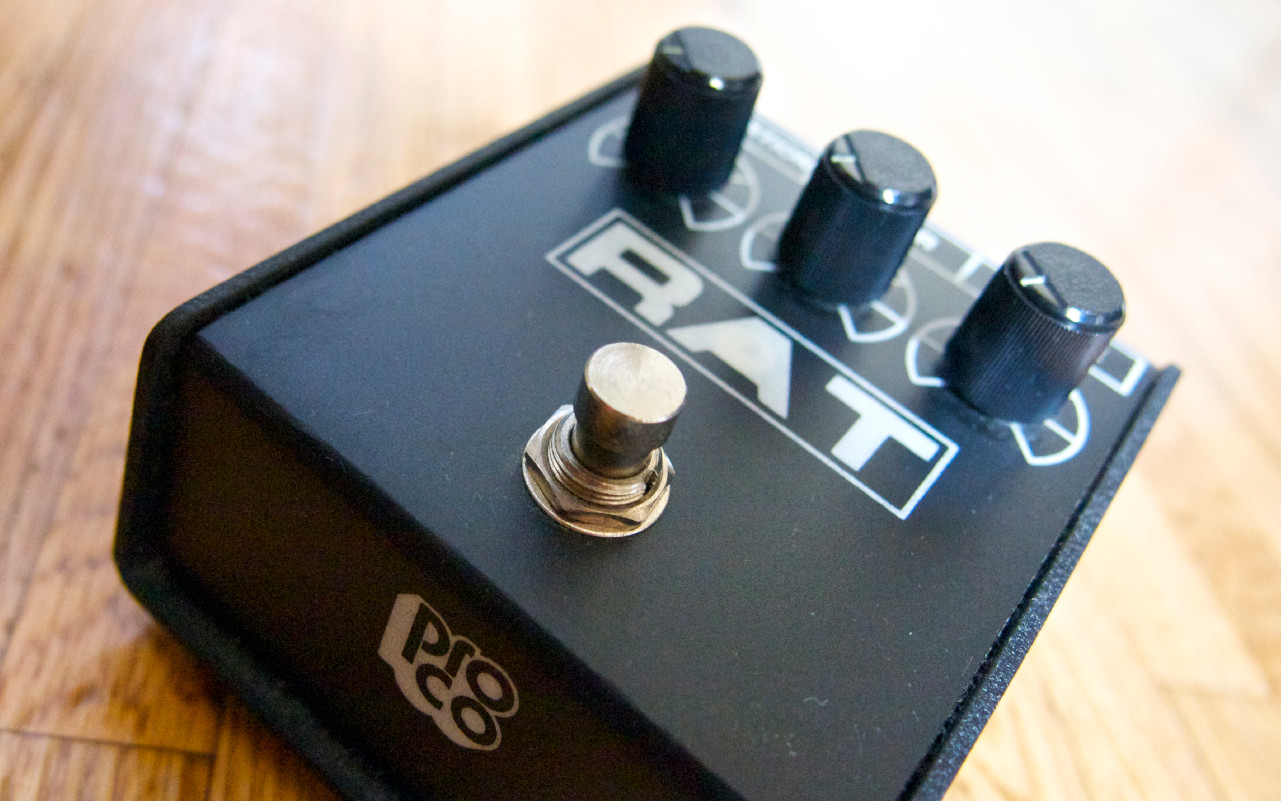
We'll be basing out build on the ProCo Rat II, which is about as primitive as clipping distortion goes, this also saves us from having to design a complicated tone stack given that the original's Tone control is mostly a low-pass filter so, in a way, the same effect can be achieved by just using the tone control from our guitar/bass.
The Build
Here's a schematic I found on Stomp Boxed:

I'm not a huge fan of the whole "I'll draw the power rails as hella long lines that span the entire schematic" approach as I think it just serves as visual clutter, so I'm just using net labels instead.
Here's our design:

As always, I try to limit the number of components needed to achieve a similar sound, most notably we're lacking the parallel RC network in the main amplifier's feedback loop, so the achieved sound isn't as sonically complex as a real Rat II would be, but it should get us pretty close.
Here's some SPICE simulations to further drive the point home, first the RAT II's:

And now our build's:

As you can see, our circuit is a bit cleaner overall, which is either a good or bad thing depending on your perspective, so go ahead and try other RC values to get different results.
As for now, here's the basics on how this design works:
- As always, we start off with a simple band filter formed by R1, R2, C1 and C2, these prevent HF EMI noise from being too overpowering, while the HPF helps us AC couple the source signal without obliterating our low-end
- Once again we're using a TL072 as both, a high-Z input buffer and a high gain non-inverting amplifier. Gain is determined by (R3/R4) + 1
- C3 is there to prevent the input DC bias from being amplified, keeping our signal centered around half our supply's voltage
- In the build I showed off in my video, I actually replaced R4 with a 220 Ohm resistor, as 22 gave me a bit too much gain too soon when turning my Gain potentiometer
- Next we're using C4 to get rid of the input DC bias, this comes in handy in the very next step
- This is it fellas, the OG, the GOAT, the clipping diodes. D1 and D2 give us hard clipping of the signal determined by the diodes' forward voltage drop, you can learn a bit more here
- While those 2 fellas are cool and all, we can't just let our signal go straight out of the amp and into ground, that's called a short and would (in theory) result in infinite current being drawn which, of course, no power supply can provide as of 2026, so R5 is doing some heavy-lifting as a current limiting resistor
- When using LED's in D1 and D2, it's important to take into consideration the maximum current rating and choose R5 accordingly, given that we're using a 9V supply we can consider that as the worst case scenario at any given moment and assume that the current going into them diodes won't ever exceed 9V/R5, so in this circuit that'd be around 9mA
- Staying on topic of those 2 diodes, a larger forward voltage will effectively give us a higher dynamic range and thus, a louder signal. This can be remedied fairly easily by adding a second amplification stage or by replacing U1B's configuration into an inverting amplifier, which of course I won't do in this design as it involves an impedance calculation for the entire clipping stage in order to do properly
- With the clipping stage and some of its caveats out of the way, we move on to R5 and C5, which I'm using as a LP filter. If you oh brave soul were inclined to include a Tone knob, this is the place to do it, just replace R6 with a potentiometer and you're done
- Remember capacitor #4? That guy got rid of our DC Bias, which means we're currently working with an AC coupled signal. Let's get our bias back using R7 and prevent it from getting into our clipping stage by blocking it with C6
- U1B serves as a unity gain buffer to keep our now distorted signal nice and clean
- Finally we use C7 to (once again) remove our DC bias, R8 and RV1 form a HP filter for the output stage which we prevent from going wild by setting R8 as a 1k Ohm resistor
- RV1 is our output volume knob and, of course, sets our circuit's output impedance to 50k Ohm
That wasn't too hard, was it? If you visit my previous guide you'll see that it is a pretty similar build and it even shares the same input stage and power section. Hopefully this drives home the concept of pedals and effects being modular entities which can share subsections when required.
So, if you followed along at home you may have something akin to this breadboard:

Congrats! You finished the build. As stated in the schematic you can go wild with the diodes used in D1 and D2, experiment and see what sounds best in your setup.
Sound demos
-> coming soon™ lol
Thanks!
Thank you for reading! ♥
Hopefully you enjoyed your stay here, I'll try to write up some new guides as I release videos so keep your eyes open!
If you enjoy my work, you can always contact me via email or gift me a coffee, I do appreciate it a whole lot!